This post will be a high level introduction to SoC design with LiteX and programming in Rust. It references the example code found here1. Instructions on how to run the code are given in the readme. If you have programmed a microcontroller, know python and maybe even heard about LiteX you should be good. There is a wiki2 and a little fpga-1013 course for LiteX, this4 is a basic tutorial for the MiGen FHDL (although you dont need to write any custom logic if you just want to connect some ready-made peripherals) and the rustlings excercises5 are great for getting started with Rust. Thanks in advance to all the people involved in those projects! Credits attached at the end.
Introduction
In engineering it is generally a good idea to accomplish a task in the simplest way possible. The resulting systems will be more robust, easier to understand/maintain and obviously the design effort is reduced. A simple lightswitch has a state space that consists of only two distinct states of a mechanical switch, with each state directly connected to the state of a lightbulb. A perfect solution for controlling the lightbulb state.
However, more advanced tasks usually require for more information to be moved in and out of the system and for more processing to be performed on the data. While data processing might still be possible or even superior in an application specific solution (like a control system), the former often requires the flexibility and programmability of a computer. Although ubiquitous in modern society, the consequences of using such a complex system should not be underestimated. It usually entails that not even the designer of the system is capable of grasping the enormous state space introduced by the computer dynamics and it’s memory. Even worse, many modern solutions like advanced microcontrollers are made by companies that intentionally hide the exact functioning of the device. The designer is forced to trust (or hope) that the system will do as the company claims6. A rather sad state of affairs.
But there is hope. RiscV is an open standard for computer architecture that has gained a lot of traction over the last years. Many fully open source cores, like the VexRiscV we’re gonna use, are available to the community now. Additionally, other open source efforts in FPGA synthesis and SoC design recently made it possible to deploy custom digital circuits without the need for any closed source tooling. And lastly a new and safe programming language with open source aspects built into the ecosystem has risen in the form of Rust.
So eased by the fact that we can at least in theory gain knowledge about all aspects of our system (except for the raw FPGA silicon), we will dare to venture into territories of immense complexity and highly nontrivial dynamics. The goal will be to interface the simple state of a switch (or button/LED in this case) using the standards of the largest information network know: The Internet.
Because these standards are very involved and span several abstraction layers, we will reside to using smoltcp (a rust software crate/library), which abstracts the complexity of the TCP/IP protocol, and LiteEth, which drives the external ethernet PHY.
Design flow overview
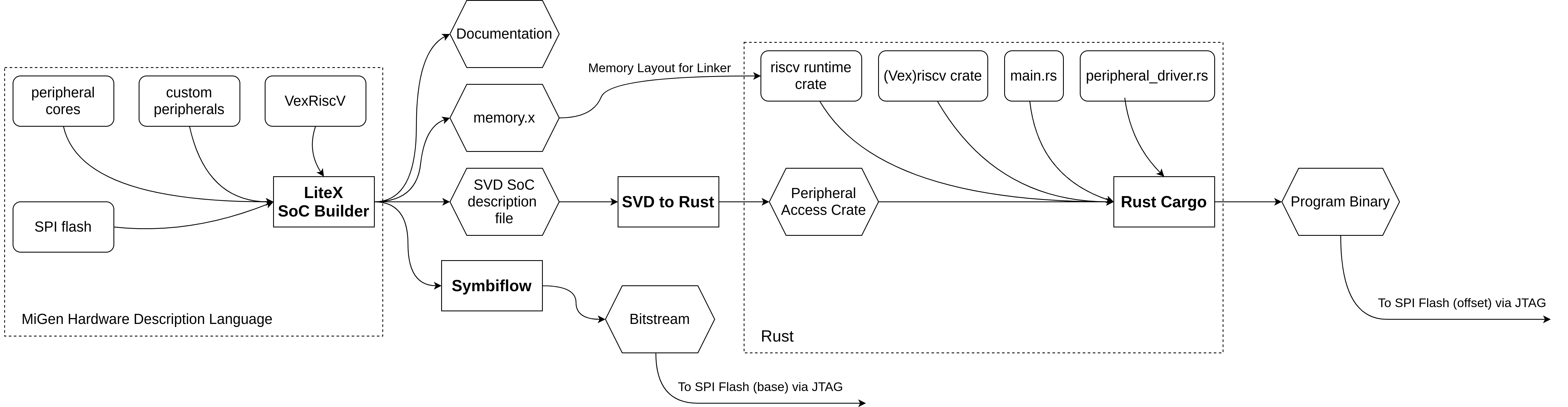
There are several intermediate steps in the process of SoC synthesis and programming. Figure 1 shows a schematic overview of the design-flow. Source files are represented by rounded boxes, tools are rectangular and the intermediate tool outputs are shown hexagonal.
 |
|---|
| (1) A basic SoC built using LiteX (open in new tab for fullscreen). |
It starts with the SoC gateware description in the MiGen FHDL (Functional Hardware Description Language). Costom MiGen and Verilog modules as well as LiteX included peripherals can be combined in the main SoC generation python file. When calling the python program with the right parameters, LiteX will automatically build all the files necessary for the successive steps. This includes the SVD SoC description, a file with SoC information like peripheral memory addresses, the memory.x file with memory layout information for the program linker and documentation for humans to read. It will also automatically call the Symbiflow tools that synthesize the SoC logic for the Lattice FPGA and even deploys it if you configured your programmer in the python file correctly.
Next step is the SVD2rust tool, which uses the SVD SoC description to generate a Rust PAC (Peripheral Access Crate). Using this PAC, peripheral drivers can interact with the gateware and abstract the underlying register accesses to simple API functions like led.on(). The main Rust program can also use other Rust crates like the VexRiscV crate that provides further functionality to control the CPUs low-level functions like interrupts. Higher level crates can provide libraries for complex tasks such as the ethernet connection with TCP/IP that we want to achieve. The rust files are then compiled for the embedded RiscV CPU by the rust cargo tool using the rustc compiler. Finally the program binary can be written to the program ROM area in the SPI flash.
SoC design in LiteX
LiteX is an SoC description framework built on the MiGen FHDL and MiSoC, another SoC design tool. It provides designers with several utilities and modules for SoC development. Infrastructure such as buses, streams, timers, Integrated Logic Analyzers (ILAs) and connectivity can be specified in Python while repetitive tasks such as bus topology and memory mapping are automated. Several included RiscV and OpenRISC soft-CPUs can be connected to an ecosystem of included peripherals including: UART, SPI flash, LiteEth, LiteDRAM, LitePCIe and many more. Additionally, LiteX-Boards7 makes it easy to deploy the SoC to a target using a few parameters when calling the python script that also builds the SoC.
The example code targets the Colorlight 5A-75B, a ~12$ LED panel driver board featuring a Lattice ECP5 FPGA that can easily be used as a general purpose FPGA board using the exposed JTAG header. It also provides 2MBit SDRAM, 32Mbit SPI flash and two Gbit ethernet PHYs. You can find a full description plus pinouts here8. It should be relatively easy to deploy the code on another target with similar specs.
 |
|---|
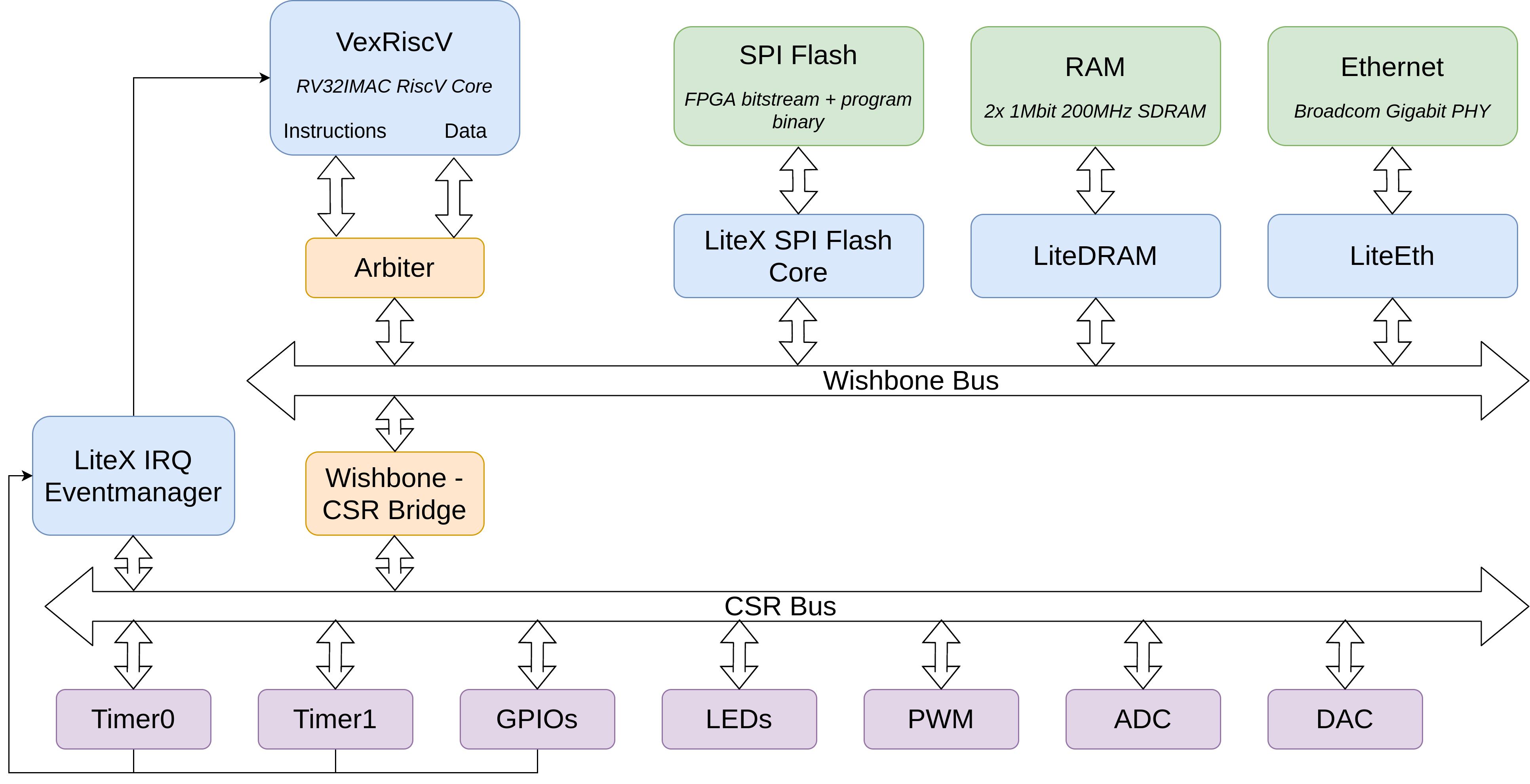
| (2) A basic SoC built using LiteX. |
Figure 2 shows an overview of the SoC built in LiteX. The CPU and main peripherals are blue, bus infrastructure is orange, external hardware green and CSR peripherals are purple.
The main Wishbone computer bus connects the memory-mapped peripherals to the RiscV CPU via an arbiter that handles the bus access by the CPUs native instruction and data connections. The program is stored in the SPI flash with an offset to give room for the FPGA bitstream at flash address 0x0. When the core fetches instructions, it performs an SPI flash access through the arbiter, the wishbone bus, the SPI flash core and finally the external SPI flash. The external SDRAM is also directly available to the CPU as the main RAM just like the ethernet TX and RX buffers.
The other peripherals are interfaced by CSRs (Control Status Registers). The CSR bus connecting them has a smaller address space and a more basic structure. It is exposed as a subset of the cores memory space via a Wishbone-CSR bridge. LiteX makes it very easy to connect peripherals via CSRs in a few lines of code, handling all of the memory mapping and description for software in the SVD file.
Finally there is the LiteX IRQ (Interrupt ReQuest) Eventmanager that dispatches an interrupt event to the CPU and connects to the VexRiscV “vmip” (Machine IRQ Pending register). When the machine interrupt flag is set in the CPU it will halt program execution and the interrupt can be handled. The Eventmanager has its own CSRs that can be accessed by the ISR (Interrupt Service Routine) to reset an interrupt state.
SoC programming in Rust
Again, thanks to the amazing community, it is very easy and convenient to program the custom SoC in Rust. The Rust cargo tool (together with the svd2rust crate) automatically checks if the SVD file changed since the last compilation and regenerates the Rust PAC code if necessary.
To write a driver for a custom peripheral we just access the peripherals CSRs (that share the same name as in the python SoC description) via the PAC in the right way. For example we could just set the correct bit in an output register of an LED peripheral or the pulsewidth register for a PWM peripheral. Of cause more complex peripherals might require for more things to be handled by the driver like consecutive register writes or writes depending on a register state. An example here would be to toggle an LED: First we read the LED peripheral register and depending if the specific bit was set or not we set or reset it.
The interrupts function in a slightly more “raw” fashion than what you might be used to from a standard microcontroller. You have to provide a fn MachineExternal() function with the #[no_mangle] attribute to tell the linker to put this code where the CPU will go if an external machine interrupt occurred. Inside the function we now check which peripheral produced the interrupt and go to the respective ISR. Finally, the ISR handles the function that the interrupt is supposed to trigger. In the example code the interrupt is triggered by an external button via a GPIO peripheral and the ISR dispatches the information to the main function which will then send a TCP packet via ethernet. Another example could be to have a real-time system triggered on a timer interrupt to perform tasks in a synchronous fashion. In the example code an LED is toggled in an ISR triggered by a timer.
The smoltcp crate is a lean and easy-to-use library that abstracts the TCP/IP network stack. It provides the basic ethernet configuration and standard TCP or UDP sockets that you can use in you program. The example code uses a single TCP server socket for an external TCP endpoint to connect to. If the connection is successfully established it will listen to commands like turning on an LED or telling a joke. If the button ISR was called and the TCP connection is established, it will notify the client when the button has been pressed. There is also a UDP server that will send a UDP packet with “Hello World!” if connected to.
Wrapping up
Using a whole stack of tooling and libraries from the open source community, we were successful in connecting the button and LED via ethernet. Obviously this just a dummy example for demonstrating the various aspects of the design process. Based on this you could provide more advanced systems with the flexibility of a CPU and ethernet connectivity. Other branches in the example repository contain code for on-SoC ADC/DAC testing and a real-time temperature controller streaming data via TCP packets.
Just a few years ago something like this was only achievable using closed source devices and software. The last step to a truly open chip would be to exchange the underlying (closed source) FPGA silicon for an open source ASIC (Application Specific Integrated Circuit). This is an enormous effort currently being undertaken by the community with help from Google in the form of the skywater-pdk9. Hopefully in a couple of years the tools and manufacturing opportunities for fully open SoCs will be further developed and become accessible to everyone.
Thanks to these people
- Sébastien Bourdeauducq for MiGen and MiSoC
- enjoy-digital for LiteX
- Gatecat and Clair and everyone else at YosysHQ for Symbiflow
- Whitequark for smoltcp
- Piotr Esden-Tempski for the icebreaker examples
- DerFetzer for the Colorlight code
- Bunnie for the Precursor code
And everyone else that contributed to these projects!